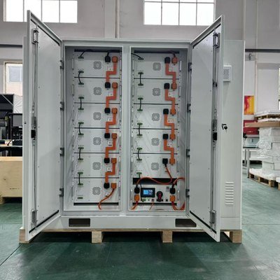
Introduction
The hardware parts and components of a C&I energy storage system do not only include the battery and inverter. An entire system has a total storage, battery management, power conversion, energy control, electrical protection, thermal management, safety, and monitoring. The project’s power, energy, grid connection, environment, and application influence their choice and integration.
C&I Energy Storage Components: A Functional Map
C&I systems make for easier evaluation when their components are grouped by function rather than listed as separate products. Distinctive layers like energy storage and system monitoring exist in the C&I BESS components. It helps buyers understand what function is performed by what component of the system.
| Functional layer | Main components | Primary responsibility |
|---|---|---|
| Energy storage | Battery system | Stores and delivers DC energy |
| Battery management | BMS | Monitors and protects battery operation |
| Power conversion | PCS | Controls AC/DC power conversion |
| Energy control | EMS | Coordinates system energy flows |
| Electrical interface | Protection, switchgear, metering, transformer | Connects and protects the system |
| Thermal/environmental | Cooling, HVAC, enclosure | Maintains operating conditions |
| Safety | Detection, isolation, fire-safety systems | Responds to abnormal conditions |
| Monitoring | Gateway, monitoring platform | Collects data and operating status |
The layers together define the C&I energy storage system components, and not each device as an independent product. NREL also identifies that the battery modules, enclosure, PCS, cooling system, BMS, meters, and ESS gateway are the building blocks of an integrated energy storage system.
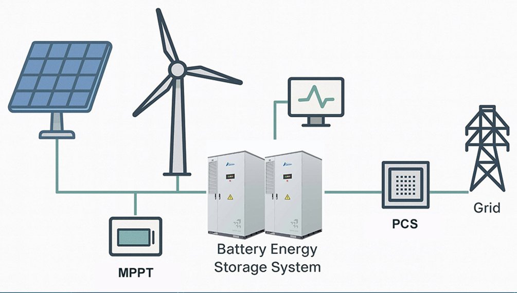
Refer to HBOWA’s Battery Energy Storage System page for the necessary broader system context.
How C&I Energy Storage System Components Work Together
A C&I system functions through interfaces rather than isolated components. The DC energy is stored in the battery. The battery management system will monitor the operating condition and set limits. The BMS sends relevant status to the PCS, which manages the electrical conversion and power response.
At the system level, the EMS coordinates the overall energy strategy based on operating information from the battery system, PCS, facility, and meter. The meter provides measurements of site or grid conditions to provide the EMS with relevant information for control. On the other hand, the thermal system adapts to the working conditions of the battery to create the required conditions for stable operation.
C&I BESS architecture is determined more by interface design than by component selection because of these relations. The functions of electrical interconnections, control signals, communication protocols, operating limits and protection must be interoperable. NREL’s system for evaluating energy storage systems and energy management systems recognizes them to be integrated systems that require coordination of equipment, controls, testing, and operating limits.
A component can meet its own specification and still be unsuitable if it is unable to communicate correctly or operate within the other component’s limits. Thus, the engineering question is not whether the necessary components are present in the BESS. It is whether the electrical, control, communication, thermal and protection interfaces are coordinated.
What Should Buyers Evaluate before Investing in Battery System in a C&I BESS?
About C&I battery storage, the battery must not be evaluated by its nameplate capacity, but as part of the complete system. To begin with, you will start with nominal and usable energy, then after the battery, check the voltage range, and so on.
Temperature conditions (of the battery) matter as they influence performance and degradation. It is recommended not to compare cycle-life figures without the test basis but to review degradation assumptions, end-of-life capacity definition and warranty conditions. The lithium iron phosphate battery chemistry is widely used in the stationary storage and the IEA says that LFP represented nearly 90% of globally deployed battery-storage in 2025.
Finally, check BMS and PCS compatibility, including voltage limits, communication, and control on requirements. Consequently, comparable nominal kWh ratings may offer different usable performance.
BMS vs PCS vs EMS: What Does Each System Actually Control?
BMS, PCS, and EMS have dissimilar functions with different responsibilities. A battery management system manages the battery’s condition and protection, but the PCS is responsible for the conversion of AC power to DC power, while EMS is used for coordinating system-level energy operation.
| Component | Primary responsibility | What it does not replace |
|---|---|---|
| BMS | Battery monitoring, protection, balancing, SOC/SOH management | Site-level energy scheduling |
| PCS | AC/DC conversion and power control | Cell-level battery protection |
| EMS | Energy dispatch and system coordination | Cell-level protection |
| Meter | Measures electrical conditions and energy flow | Energy control itself |
| Thermal control | Manages operating temperature | Battery electrical protection |
In actual energy storage systems of C&I, these functions complement. The BMS identifies battery operation limits. The BESS PCS acts within those limits in controlling the electrical power. The EMS operates at a high level by coordinating the operational strategy according to system conditions and project needs.
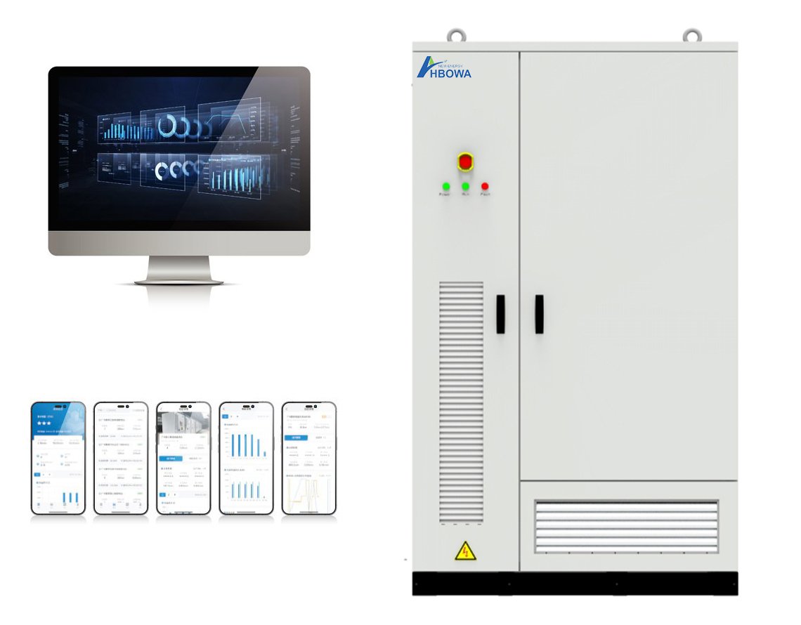
As a result, the BMS does not replace the EMS, nor does either control layer replace the PCS. When assessing BESS components, communication interfaces, and system controls, it is vital to segregate functions. It also explains why a commercial system needs multiple coordinated control layers rather than just one normal controller.
Electrical Interface Components in a C&I Energy Storage System
Electrical interface components establish essential links between storage systems and the grid or facility. These procedures may include DC disconnects, AC/DC protection, AC switchgear, electrical metering and a transformer where the project requires it.
The selection is dependent on various factors including system voltage and current, PCS rating, point of connection, facility electrical architecture and applicable grid requirements. Protection devices should be aligned with the equipment they safeguard. Even though a component has the correct nominal rating, it may still be unsuitable due to its protection characteristics not being suitable for other components in the installation.
When system control relies on measured facility or grid conditions, energy storage metering takes on added significance. Higher-level controls can use the operating data provided by the meter.
In bigger installations, a transformer might be required to match BESS with site connectivity. According to Fraunhofer ISE, the integration of storage systems with medium-voltage grids can be aided by power electronics.
For substation-level architecture, refer to HBOWA’s Battery Energy Storage System Substation.
Thermal Management and Safety Components in C&I BESS
In C&I BESS, thermal management and safety should be a connected layer of protection and not an accessory. The equipment used to cool the battery measures the temperature while it is operating. Should unusual situations arise, monitoring, electrical protection, isolation, detection, and fire-safety measures offer extra layers of response.
This relationship is important because thermal processes can involve several parts of the system. As a result, battery thermal management cannot be specified as an HVAC system function; it will need to work with battery monitoring and protection functions.
The installation also influences safety requirements. The NFPA 855 standardized guide for stationary energy storage installation provides provisions for fire protection, detection, suppression, ventilation, gas detection, and thermal runaway.
Because of this, buyers have to check the thermal and safety equipment against the technology and location of the project, the design of the installation, and the requirements. All this rather than one specification.
How C&I Project Requirements Change Component Selection
The ideal design for a C&I BESS project begins with the project and not a component list. A facility that has a high peak demand may need a different PCS and battery configuration than a site needing longer discharge durations. An already operational PV installation might also require distinct controls and interfaces different from a standalone project, concurrent with storage.
| Project requirement | Components affected | What changes |
|---|---|---|
| High peak power | -PCS -Battery | -Power Capability -Discharge Performance |
| Long discharge duration | -Battery System -Thermal System | -Usable energy and thermal requirements |
| Existing PV retrofit | -PCS -EMS | -Compatibility -Control Architecture |
| High ambient temperature | -Cooling -Enclosure -Battery | -Thermal management requirements |
| Outdoor installation | -Enclosure -Protection -Cooling/Ventilation | -Environmental protection |
| Tight grid connection | -EMS -Meter -PCS | -Control and measurement requirements |
| Future expansion | Battery and PCS architecture | Modularity and scalability |
| Critical loads | -Protection and controls | -Backup and transfer requirements |
| Remote installation | -Monitoring and communications | -Diagnostics and serviceability |
Choosing an energy storage system is a decision that needs engineering on a project basis. The final configuration is affected by the load profile, rated power, usable capacity, site conditions, connection requirements, and operating strategy.
The storage-planning job at Fraunhofer ISE works in a similar fashion. The approach will develop storage applications taking into account existing and planned generators and consumers, conditions for connection, site factors, and technical and regulatory requirements.
As a result, two commercial battery storage projects with the same energy capacity may require different components, ratings, controls and installation arrangements.
What Specifications Matter Most for Each C&I BESS Component?
The data sheet of the components should be evaluated at the system level. One of the most useful and important aspects is whether each device has a specification that can satisfy the electrical, control, environmental, and operating requirements to complete the entire project.
| Component | Specifications to compare |
|---|---|
| Battery | -Usable energy -Voltage range -C-rate -Degradation basis |
| BMS | -Monitoring -Balancing -SOC/SOH -Protection -Communication |
| PCS | -Rated Power -Voltage Range -Overload capability -Efficiency |
| EMS | -Control Functions -Meter Integration -Communication -Remote control |
| Cooling | -Cooling Method -Operating Range -Auxiliary Consumption |
| Protection | -Voltage/current Ratings -Fault Protection -Isolation |
| Monitoring | -Data Points -Alarms -Protocols -Remote Access |
When comparing specifications in BESS selection, it needs to be performed under the same testing conditions and definitions, such as the battery capacity from usable energy and the power of the PCS from the operating range and the voltage at which it wants to operate.
This method makes a data sheet only a pile of numbers for the compatibility check. Many people make a simple rule of selecting BESS by checking the highest individual specification component, but in real-time, the project requires many BESS components simultaneously.
Common Mistakes When Evaluating C&I Energy Storage Components
Selecting battery capacity before examining the load profile of the facility is a common mistake. kW and kWh are often interchangeable, even though those values represent different requirements of the system. Sometimes, people can get confused about the role of BMS and EMS as well.
Many people overlook the ambient temperature for thermal requirements, so the purchase should be evaluated regularly. Battery prices don’t provide good insight, since the PCS, Protection, Controls, Installation, Service, and lifecycle conditions are often not included in the analysis; the lowest component price is more likely not the lowest system cost or the best technical fit.
Real C&I Example: Why Component Selection Must Follow the Application
HBOWA’s 200 kW / 576 kWh BESS project in Malaysia, designed for peak shaving, is a useful first-party example. Its 200 kW is the power rating of the system. On the other hand, its 576 kWh is its energy capacity. So, the two can generate different sets of engineering questions.
For example, the above case is why battery capacity alone cannot define a C&I energy storage system. The required battery, PCS, controls, electrical protection, and operating strategy must operate to serve the actual power and energy requirements of the project.
This data example is from the HBOWA project is not from an industry benchmark. It is helpful to select components based on the application and operating requirements, without setting a predetermined battery configuration.
Where C&I Components Are Integrated: Cabinet or Container?
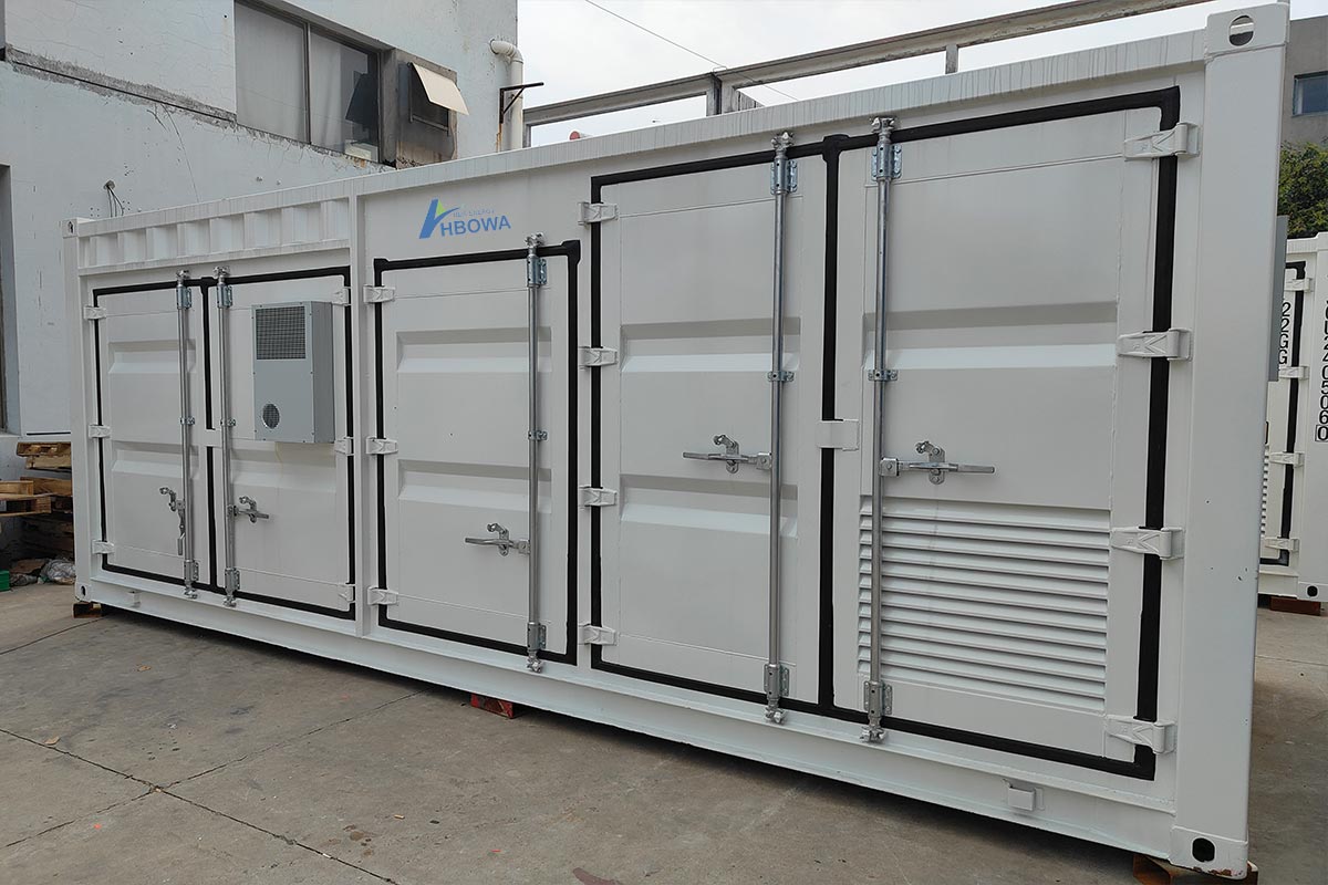
Battery management system (BMS), protection equipment, PCS, battery system, cooling, and EMS are integrated into the power energy storage cabinet and BESS container. The format is selected according to the power, energy capacity, available space, installation conditions, and requirements for expansion. Visit the Energy storage cabinet and BESS container pages of HBOWA for more information about them.
C&I BESS Component Selection Checklist
A practical B2B C&I BESS Component Selection would require all devices to be tested against full project specifications. For the battery, check the capacities, voltage range, C-rate, degradation assumptions, as well as any warranty terms and conditions. The BMS should be tested for its Monitoring, SOC and SOH functions, protection, as well as communication. The PCS should be rated based on its Power, rated voltage and current range, overload, and whether it is grid-certified.
The EMS should be tested for energy control, meter integration, PV and Grid / Load coordination, and remote monitoring. The electrical system should be tested for the Protection, switchgear, metering, and transformer requirements, if any. Conditions of temperature, cooling, enclosure design, and the site environment should be checked too.
This is a practical framework to categorically shortlist a set of best C&I BESS components a firm would require, rather than another general list of BESS components.
Conclusion
The components of a C&I energy storage system combine into an integrated architecture, rather than being standalone products. Together, the battery, BMS, PCS, EMS, electrical interface, thermal management, safety, and monitoring need selection. According to the protection and grid connection to which each component must be adapted, the project’s power, energy capacity, site conditions, mounting, and operating conditions must be reliable.
Frequently Asked Questions
A storage system for C&I energy can make use of these communication protocols, namely CAN, RS485, Modbus RTU, and Modbus TCP/IP, as per the equipment and system architecture. The BMS may be able to communicate battery data to the PCS, while the EMS may gather data from the BMS, PCS, smart meters, and other site equipment. Buyers and EPCs must ensure the compatibility of the protocol, communication interfaces, data points, and control commands supported before integrating.
Battery and system power density, heat generation, ambient temperature, enclosure design, and installation conditions determine the cooling selection. Air cooling can be best for many lower-density systems with manageable heat load, while liquid cooling is better for providing controlled and homogeneous thermal management when higher cooling requirements are demanded with higher system density or operating conditions.
As per the system architecture, there are independent replacements or upgrades available for several components. The replacement component must match the required electrical ratings, communication interface, control logic, firmware version, protection settings, and physical connections.
The EPC can check the electrical ratings, communication compatibility, control hierarchy, protection coordination, environmental requirements, and installation conditions of each component. This includes battery, BMS, PCS, EMS, metering equipment, switchgear, cooling system, and safety equipment. The EPC can go through single-line diagrams, communication maps, equipment datasheets, commissioning procedures, certifications, and warranties before the final selection of the equipment.
Ambient temperature, humidity, dust, altitude, and ventilation all influence component selection in C&I energy storage projects. High temperatures accelerate battery aging and reduce usable life, so the cooling method, thermal management design, and enclosure protection must match the actual installation environment. For harsh sites, buyers should also review corrosion protection, ingress protection (IP) ratings, and monitoring coverage so that the battery, BMS, PCS, and safety equipment keep operating within their specified conditions.