
Formula: VA = A × V
It is essential for UPS systems, transformers, generators, inverters, and commercial electrical panels. Usually, their capacity will be in VA, not amps. Users can find out the real electrical load that has been applied to the system by entering current, voltage, and one-phase or three-phase supply. It prevents the overload, incorrect sizing, and unsafe installation of equipment.
Formula & Variable Definitions
Single-phase System
VA = A x V
Where:
VA is Apparent Power (Volt-Amperes)
A is Current(Amperes)
V is Voltage(Volts)
Three-Phase System
VA = √3 x A x V
Where:
√3 is 1.732(Phase multiplier)
A is Current per phase(Amperes)
V is Line-to-line voltage (Volts)
These formulas explain the relationship between apparent power (VA), voltage, and current in an AC system. The amount of electrical power taken from a source is called volt-amperes (VA). Essentially, volt-amperes are a measure of the real power, which is the usable work and the reactive power created by inductive devices (motors, compressors, switching power supply converters, etc.) that do not contribute to the useful work.
Amps (A) are the units of electrical current. Cable sizing, breaker ratings, fuse protection, inverter output limitations, and overall thermal performance of the system will be affected directly. Electrical potential supplied by a utility connection, a generator, or an inverter system is measured in volts (V).
In single-phase systems, the voltage and current can be multiplied to obtain the apparent power. In a balanced three-phase system, the √3 multiplier reflects the connection between the conductors so that more power can be delivered without increasing current.
This relationship is valid for an AC system when its voltage is stable and the load is balanced. This is the basis on which generator sizing, UPS capacity, and commercial power distribution are done.
Example Calculation
A three-phase 415-volt supply is used in a ventilation system of a commercial building, and according to field measurements, 18 amps is drawn on each phase during steady operation, so initially, 18 amps doesn’t seem like a lot. However, once this current is converted into apparent power via amps to volt-amps three-phase supply, the actual electrical demand becomes clear.
The electrical system must supply almost 13,000 VA due to the combined impact of voltage, current, and phase interaction.

This value is essential for choosing the transformer or backup generator capacity. If only the current vale were used as it is and not converted to VA, then the supporting equipment may be undersized, which may cause overheating, voltage instability, and breaker trip issues.
This shows why you should always convert amps to VA during system planning instead of working with readings taken from the field.
When to Use This Calculator
This calculator is useful whenever electrical measurement in amps is made, but system capacity or equipment ratings are given in volt-amperes. Such situations are quite commonplace in practical installations. Electricians, engineers, and solar technicians frequently utilize clamp meters to measure current while working on equipment, and the equipment they are connecting to, such as UPS systems, transformers, generators, and inverters, lists limits in VA. Until you convert the amps into VA, you cannot know if the system will handle this safely.

This can be particularly useful for panel upgrades, equipment additions, back-up power planning, inverter, or generator selection. The difference between current and apparent power in commercial and industrial environments with a three-phase supply is bigger. A simple reading of current could translate to a very large VA demand with voltage and phase relationships in consideration. This calculator is a tool that can help overcome that problem by transforming field measurements into useful capacity values that can be directly compared to equipment specifications.
Reference Table (Typical Values)
| Amps (A) | Voltage (V) | Phase | Apparent Power (VA) |
| 4 A | 120 V | Single | 480 VA |
| 6 A | 230 V | Single | 1,380 VA |
| 9 A | 240 V | Single | 2,160 VA |
| 12 A | 277 V | Single | 3,324 VA |
| 18 A | 120 V | Single | 2,160 VA |
| 22 A | 230 V | Single | 5,060 VA |
| 5 A | 400 V | Three | 3,464 VA |
| 8 A | 415 V | Three | 5,751 VA |
| 10 A | 380 V | Three | 6,582 VA |
| 14 A | 415 V | Three | 10,062 VA |
| 18 A | 415 V | Three | 12,940 VA |
| 22 A | 400 V | Three | 15,238 VA |
| 28 A | 415 V | Three | 20,118 VA |
| 32 A | 415 V | Three | 22,985 VA |
| 36 A | 480 V | Three | 29,905 VA |
| 45 A | 480 V | Three | 37,412 VA |
| 60 A | 415 V | Three | 43,092 VA |
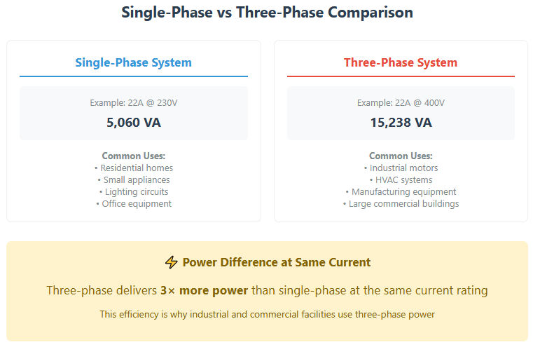
This table shows that for three-phase systems, the apparent power increases drastically while the current is moderate. The √3 factors make it possible to deliver a higher total power using much less current, thus allowing for a reduction in conductor size.
This is the reason that industrial equipment, HVAC, and manufacturing equipment largely work on a three-phase supply, which can transfer high-power capacity while working with better stability and efficiency.
Accuracy & Limitations
The calculation assumes fixed voltage and symmetrical electrical conditions. In real-life, the voltage can change as the load varies, the cable gets longer, the battery discharges, or the generator regulates to this load. When the voltage changes, the apparent power demand changes, but the current reading seems to be the same, but the actual operating VA may slightly vary from the computed value.
In three-phase systems, the method assumes all three phases have equal load. Systems in older installations often experience phase imbalance, often resulting in one conductor carrying heavier current than others. Electrical stress is amplified, and the rise in temperature can’t be known from average readings.
Inductive devices like motors, compressors, HVAC, and others use higher apparent power at startup than in steady state. Simple readings of current do not capture the brief surges of increased load, which must be considered during the sizing of generators or transformers.
Due to these reasons, the result of the A to VA calculator should be considered as a useful guide for planning and verification. Professionals usually add a design margin above the calculated VA for voltage variation, starting surges, conductor resistance, and aging of the system.
| Region/Country | Single-Phase Voltage | Three-Phase Voltage | Frequency |
|---|---|---|---|
| US United States / Canada | 120V / 240V | 208V / 480V | 60 Hz |
| GB United Kingdom / Ireland | 230V | 400V | 50 Hz |
| EU European Union | 230V | 400V | 50 Hz |
| AU Australia / New Zealand | 230V | 400V | 50 Hz |
| IN India | 230V | 400V | 50 Hz |
| CN China | 220V | 380V | 50 Hz |
| JP Japan | 100V | 200V | 50/60 Hz |
| BR Brazil | 127V / 220V | 220V / 380V | 60 Hz |
Case Study
A fabrication workshop plans to install a backup generator for use by cutting machines; ventilation motors, lighting, and control electronics working on 400-volt three-phase. During peak activity, the average current draw was found to be 22 amps per phase.
Initially, the team thought of choosing a 12 kVA generator since the readings did not look much. However, further Amp-to-VA conversions for a three-phase system showed that, under normal operating conditions, the actual apparent load exceeded 15 kVA.
The machine was started, and the current at startup briefly went over the limit, thus further increasing the apparent demand. A 12 kVA generator would have been an overloaded generator capable of causing a drop in voltage, leading to equipment misfiring and overheating of the generator.
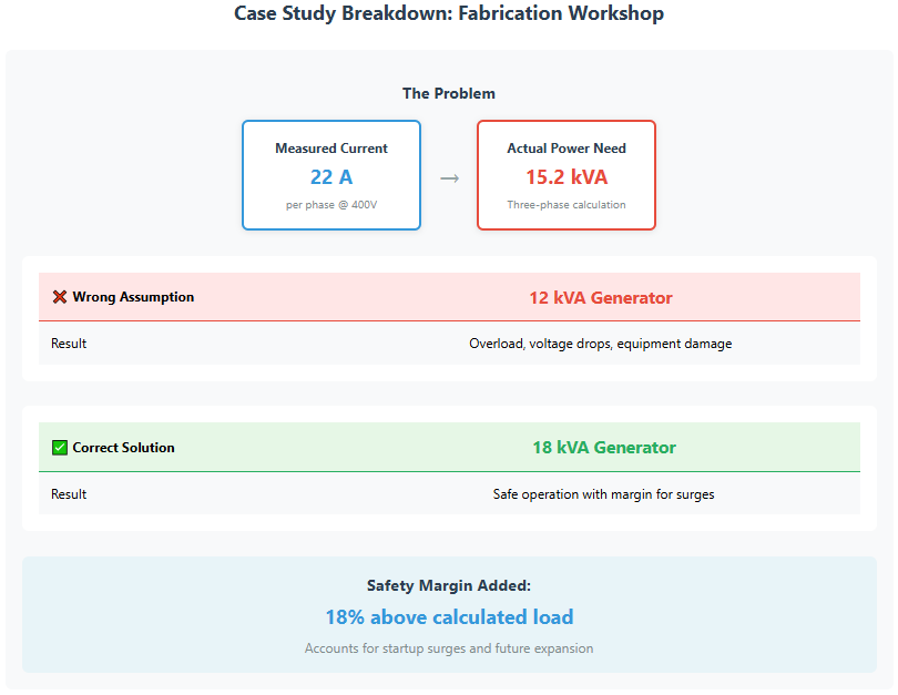
The understanding of the relationship between volt-amps vs amps made the team upgrade the plan to an 18 kVA generator. The extra capacity was enough to accommodate start-up peaks and future equipment. The system functioned reliably during outages, and no overload conditions occurred.
This case demonstrates how the correct amp to VA conversion stops costly undersizing mistakes to increase longevity.

Conclusion
The A to VA calculator is a vital link between real-world electrical readings and equipment capacity ratings. Making use of the formula converts amps to volt-amperes for either single-phase or three-phase, allowing users to see the true electrical demand placed on transformers, generators, inverters, and UPS units. This prevents under-sizing, reduces overload risk, and improves electrical design decisions safety-wise.
More Calculators for You
Frequently Asked Questions
VA represents apparent power, which includes both usable and reactive components in an AC circuit, and for more in-depth information, please read the section “Formula and Variable definition”.
No, amps measure current flow, while VA measures total electrical load based on voltage and phase.
Because they must handle total electrical stress, not just real power consumption.
No, VA is specific to AC systems only, and that is another reason we don’t use PF in the formula, and DC systems use watts for power measurement and thus use the PF in it.