
Introduction: What Does a Battery Energy Management System Do?
A Battery Energy Management System (EMS) is the controlling layer that coordinates a battery ESS with the PCS, solar PV, grid and site loads at the system level. The energy management system specifies when to charge or discharge, as well as when to remain idle, based on the operating conditions, battery limits, available power, and energy-management objective configured in the system.
What Is a Battery Energy Management System?
A Battery Energy Management System regulates the usage of electricity, which is stored in a BESS. It integrates operational data from the battery, power conversion equipment, generation sources, loads, meters, and grid connection to manage the flow of power at the system level.
In contrast to a BMS, which just monitors battery condition and enforces battery operating limits, the EMS deals with the bigger energy strategy. The PCS or inverter, PV generation, site demand, grid exchange, schedules, and metering information can be coordinated.
Basically, the EMS identifies how the device is expected to function given the limits of other hardware. It does not become a BMS or PCS. The battery management system provides battery protection, and the PCS in real time controls the electrical power conversion. The EMS coordinates these functions towards a configured operating objective.
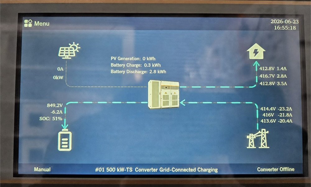
An EMS matches battery capacity to site-specific energy needs, responding to inconsistent demand and supply, while scheduling generation and load to maintain system equilibrium.
How EMS Fits Into a Battery Energy Storage System
A battery energy management system links battery-level control to site-level power operation. The hierarchy of a battery energy storage system can be simplified to battery cells, then goes to BMS, then goes to EMS, then goes to PCS, then goes to grid, then goes to PV and in the last loads. Every layer is allotted a unique function along with some measurement, limit, and control signals.
| Component | Main role | Typical information or action |
|---|---|---|
| Battery | Stores electrical energy | -DC energy storage |
| BMS | Monitors and protects the battery | -SOC -Temperature -Voltage -Current -Limits |
| EMS | Coordinates system-level energy flow | -Operating strategy -Charge/Discharge commands |
| PCS | Converts and regulates electrical power | -DC/AC(conversion) -AC/DC(conversion) |
| Metering | Measures site and grid conditions | -Import -Export -Load -Power data |
Stored energy is provided by the battery. The BMS gives information about its condition and allowable limits. The EMS combines these limits with system-level information needed to define the energy-flow response. The PCS thereafter creates and regulates electrical power as commanded.
BMS and EMS are not interchangeable. The BMS monitors battery status, safeguards against hazards, and regulates performance limits. The EMS determines where the energy is coming from, where the energy is going to, and when the BESS should be working.
The Battery Energy Storage System control relationship always remains centre stage, irrespective of the project-specific architecture that may vary. IEC 62933-3-1:2025 is on EES operations, monitoring, and acquisition of the operating parameters, information exchange, and control functions.
How a Battery EMS Controls BESS Charging and Discharging
The battery energy management system’s main function is to turn operating data into energy-flow control decisions. EMS assesses conditions, checks limits, sends a command, and then uses updated measurements and data to adjust operation.
Collect operating data
The BMS, PCS, meters, PV hardware, and site controls send information to the EMS. The inputs depend on the architecture and can include the battery SOC, charge or discharge limit protocols, the status of the PCS, the PV output, site load, and web import or export. These inputs provide the BESS energy management system with an updated view of operating conditions.
Check operating constraints
The battery cannot be treated as an unlimited power supply by the EMS. Before issuing an instruction, it works within the limits given by the BMS and other equipment. Constraints such as minimum and maximum state of charge (SOC), charge and discharge limits of the battery, PCS capability, availability of photovoltaic (PV), demand at the site, grid constraints, alarms, backup reserve setting, operating mode, etc can be included.
Select the operating action
The EMS identifies the response for the operational objective. It may require charging, discharging, reduced power, or no battery action depending on the configuration. It might also deal with solar self-consumption priority, a reserve SOC, and grid imports and exports under configured limits.
Send a power command
The EMS instructs the PCS or integrated inverter of the selected operating strategy by sending a control command or power setpoint. The PCS controls electrical conversion for charging or discharging the battery as requested, while maintaining configured voltage, current, and power limits.
Measure the result and adjust
Upon application of the command, new measurements arrive at the control system. The EMS has the ability to alter the command in response to changes in PV generation, load demand, grid conditions, or battery limits.
The control loop is:
Measure → Decide → Command → Measure again → Adjust
This closed-loop approach allows battery storage management to respond to changing conditions rather than relying only on a fixed schedule.
How EMS Decides Where Battery Energy Should Go
An example is given of how a Battery Energy Management System can change its operating decision as site conditions change. In case there is a higher production of solar PV compared to the current load of the facility. The battery’s capacity is available; the BMS allows charging, and the PCS is provided with enough charging capacity. According to the configured solar self-consumption strategy, the Energy Management System (EMS) can send excess power to the battery instead of wasting that energy.
Later, the output of solar energy decreases, while demand at the site remains high. The configured reserve of the battery SOC is still available. The grid import has breached the target. The EMS can then use the PCS to request discharge to assist the site load.
Just an example; the control sequence is not universal. The EMS configuration, electricity tariff structure, grid compliance requirements, BMS limits, PCS capability, project goal, and backup reserve setting actually determine the decisions. In the event that any project operating priorities change, a BESS energy management system may make a different decision in the same PV and load circumstances.
What Data Does a Battery Energy Management System Monitor?
Essentially, a Battery Energy Management System utilizes operational data to determine what the BESS is capable of doing and is meant to do. The specific inputs differ according to architecture, communication protocols, equipment, and project setup.
| Data | Why it matters |
|---|---|
| SOC | -Shows available stored energy |
| Battery power | -Shows current charge or discharge |
| BMS limits | -Defines battery operating boundaries |
| Temperature | -Identifies relevant thermal conditions |
| PV generation | -Shows available solar power |
| Site load | -Shows current electricity demand |
| Grid power | -Shows import or export conditions |
| PCS status | -Confirms conversion equipment availability |
| Alarms | -Identifies abnormal conditions |
| Schedule or tariff data | -Supports configured time-based operation |
Battery storage management software can operate based on prevailing system events instead of just battery capacity, using these inputs. For instance, just because there is available energy does not mean there is available discharge power; the BMS or PCS has a lower limit. When assessing energy storage management systems for commercial or industrial projects, this distinction is crucial.
How EMS Manages Energy Flow Between PV, Battery, Grid and Loads
A battery energy management system coordinates multiple energy pathways instead of considering the battery an isolated asset. The main paths are PV to load, PV to battery, battery to load, and grid to load or battery. The specified operating strategy of a project determines which path gets priority.
For self-consumption of solar energy, when the generated power of the solar PV exceeds the local demand, the EMS can store the surplus power into the battery if it is eligible. The solar-plus-storage documentation of HBOWA states that solar will first serve the loads. Surplus generation then charges the BESS when conditions permit.
The coordination will be the same for scheduled grid interaction. The EMS controls charge/discharge and pre-set import or export limits, depending on the project.
Whether the energy storage takes place in an energy storage cabinet or an energy storage container, these choices are based on data from the battery, PCS, grid, PV, and load. We employed a containerized BESS EMS, with scheduled charging and discharging based on these inputs.
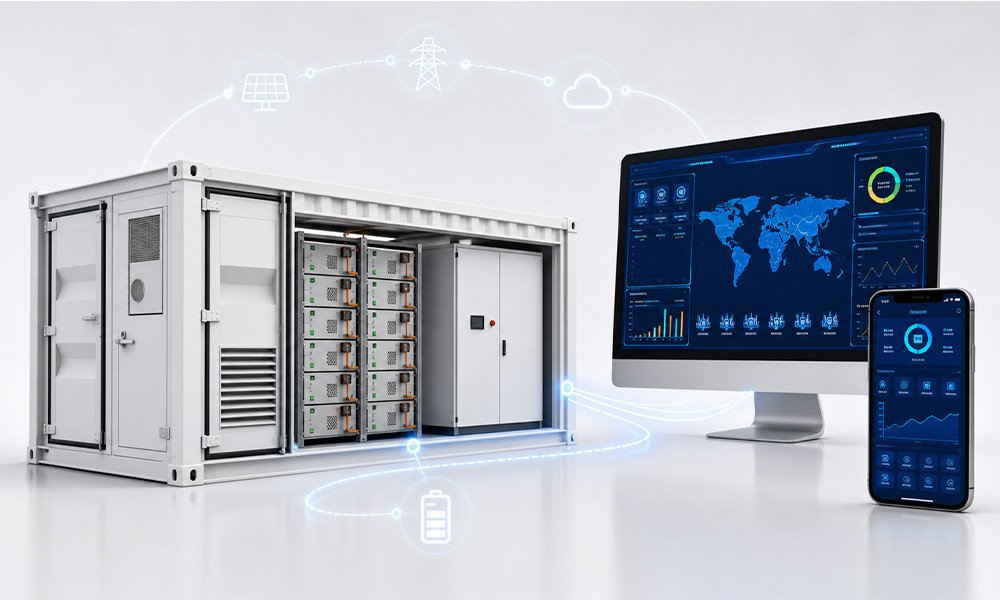
How EMS Balances Competing BESS Objectives
A Battery Energy Storage System (BESS) can simultaneously fulfill multiple objectives. These may include self-consumption, peak shaving, load shifting, backup power, TOU energy management, grid support, and zero export control. It is difficult for various objectives to compete for the same stored energy.
Think of a hotel setup designed for peak shaving and backup. If the EMS utilized all usable battery energy to reduce demand from the grid during normal operation, there wouldn’t be much left to use in case of an outage. Therefore, a proper control strategy can reserve a portion of the battery’s SOC for critical loads while using the remaining for normal operation.
Battery energy management software should be assessed by the control logic and the project configuration, not just by the monitoring interface. IEC 62933-3-1:2025 is concerned with defining EES operational, monitoring, information exchange, and control capabilities at the system level.
Battery Energy Management Software: What Should Buyers Look For?
Buyers should look past the monitoring dashboard when assessing battery energy management software. The software must accommodate the real operational needs of the BESS while ensuring dependable communication with connected equipment.
A modern energy storage software platform should offer real-time insight into the system, operating mode configuration, control over charging and discharging, state-of-charge checks, alarm-event records, history, scheduling, and energy feedback. Distributed commercial and industrial systems can also be enhanced through remote monitoring and user access controls.
It is also equally important to have interoperability. It is crucial to ensure that the BMS, PCS, energy meters, PV equipment, and site control system are compatible. Before commissioning, communication protocols, external EMS interfaces, criteria for data access, and communication loss behaviour should all be defined.
It is also important to distinguish battery storage software from monitoring software. Monitoring can indicate how the system works, while the energy storage control software must support the control functions that the project requires. The architecture must fit your system design, operational objectives, and integration requirements.
Battery EMS Integration Checklist for EPCs
When choosing a Battery Energy Management System, EPCs and B2B buyers should prioritize project requirements over the software interface for optimum results. The essential task is to outline the required operating role. A battery energy storage system (BESS) adds to solar self-consumption, peak shaving, backup power, or off-grid operation, to name a few.
The following step is to check equipment compatibility. As needed, the EMS must communicate with the BMS, PCS or inverter, energy meter, PV inverter, grid equipment, and site controller or SCADA system. Documentation of communication architecture should arrive before installation.
The system design should also agree upon operating limits. SOC limits, charge and discharge power, backup reserve, grid import or export limits, and the required control behaviour.
It is also important to consider commissioning documentation. EPCs are to finalise control logic, communication settings, alarm definitions, single-line diagram, testing procedure, and remote-monitoring requirements before handover. The HBOWA cabinet service information includes a sizing of the system, single-line diagrams, equipment configuration, communication documentation, and remote commissioning among the project-support activities.
Integration specifications shall be clearly defined to avoid ambiguity between the EMS, the battery, the PCS, and the site equipment.
Real-World Examples of Battery Energy Management
Two real-world projects illustrate application-based rather than capacity-based battery energy management. HBOWA’s C&I portfolio features a Poland 50kW/301kWh, a Romania 100kW/200kWh, and a Togo 300kW/400kWh system, as published.
The Poland project documentation is for solar self-use, peak shaving, and load shifting. The storage system must respond differently as solar production, factory demand, and grid demand change. Consequently, the initiative serves as a real-world illustration of having various operational goals within a single BESS.
The Romania hotel project features a 100kW/200kWh system for self-consumption, peak shaving, and backup. The documented modes of operation highlight a different requirement: normal energy management must coexist with backup availability.
Togo project is an off-grid system of 300kW/400kWh. This indicates that BESS energy management also changes in the case of design operation without a normal utility grid.
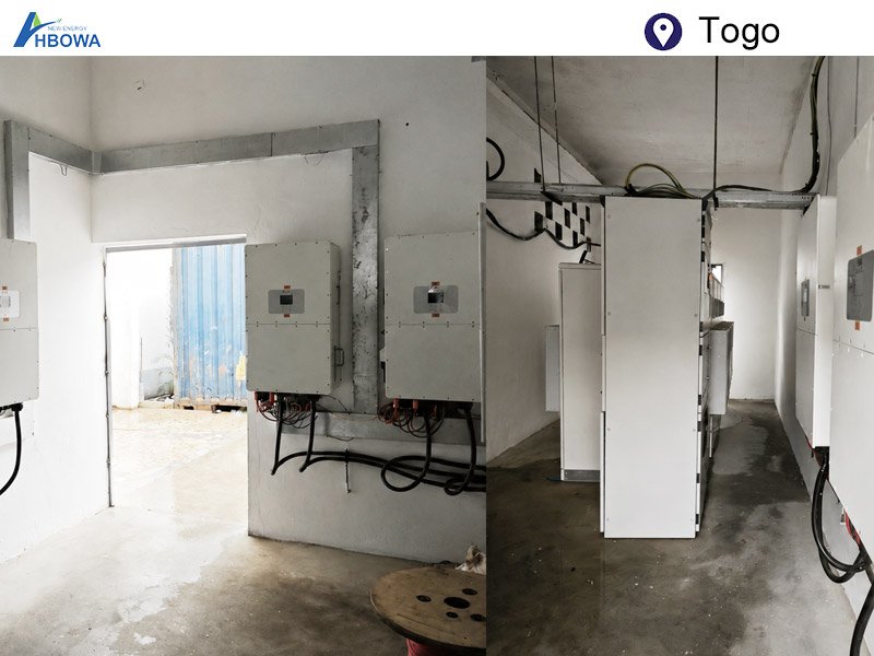
The documented project applications are described in the forthcoming examples, not in EMS algorithms and control sequences.
Conclusion
A Battery Energy Management System (EMS) for batteries extends beyond merely observing a battery energy storage system (BESS). The battery, PCS, energy resources, loads, and grid conditions are coordinated according to operating objectives. The selection of an EMS architecture must take into consideration the equipment, control requirements, operating limits, and integration strategy of the project.
Frequently Asked Questions
A BESS may contain local control functions that allow its limited operation upon failure of the communication with a higher-level EMS depending on system architecture. The battery, BMS, PCS, inverter, and site controller each may have their own protection and fallback functions. EPCs need to validate the specified communication-loss behaviour before commissioning, rather than assuming each BESS behaves identically.
It is possible for one properly designed control architecture to coordinate multiple BESS units. The precise configuration relies on the PCS, BMS, communication interfaces, site controller, and EMS architecture. There may be a high-level controller within a plant or site for larger projects and systems. The design is intended to define how power commands, limits, alarms, and system status are exchanged between the units.
No. The core control function is not necessarily reliant on cloud connectivity. The design will rely on project requirements, cybersecurity rules, availability of communication, along with the functions that need to be available during an external network failure.
The scheduling refers to the defined intended operating periods or targets, like charging or discharging. Real-time control is a mechanism that reacts to the actual situation. The planned operation may need to be changed by the energy management system in the event that the site load, PV output, the grid conditions, or equipment limits require it. For this reason, a schedule should instead be seen as an operating instruction within system limits, not a guarantee that the battery will constantly operate at a fixed power.
The EMS must take action if a battery reaches a configured upper or lower SOC boundary. At a high state of charge, further charging may be limited or stopped. Discharge might be diminished or stopped at a low SOC. The PCS controls, EMS settings, project operating mode, and BMS limits will determine the exact response. The usable operating range is defined during system design, rather than inferred from nominal battery capacity, as this shows.