Formula:
DC: A = W ÷ V
A V to A Calculator converts V to A by changing voltage and power to current, which it measures in amperes. It is important to determine how much current a device, appliance, battery system, or solar component will draw in operating conditions. This calculator has been designed by HBOWA for electricians, engineers, solar installers, and students, as well as anyone with a need to size wires, breakers, inverters, or batteries. When a voltage (V) and a power (W) are inserted, users can quickly find out what current (A) is expected for a safe and efficient system.
Formula & Variable Definitions
Basic DC& Single-Phase AC Formula
A = W / V
Single-Phase AC with Power Factor
A = W / V x Power Factor
Three-Phase AC Formula
A = W / (V x Power Factor x √3)
The following formulas show how power, voltage, and efficiency govern the amount of current flowing. Equipment under operating conditions consumes real working power measured in watts. The volts represent how much electrical potential is being supplied by the battery bank, inverter, generator, or utility connection. Amps are a measure of how much current a load draws. It impacts everything from cable size to breaker rating to fuse rating to inverter rating to battery discharge rating.
For practical electrical and solar installations, these equations help get the accurate current value from appliance nameplate ratings and inverter specifications. The fundamental formula holds true for DC systems like Lithium battery banks, solar charge controllers, as well as resistive AC loads. In most AC systems, motors and compressors need the power factor for an accurate current demand estimation to prevent underestimating. Under balanced conditions, three conductors carry power, which is why three-phase systems require the √3 multiplier.
Example Calculation
An off-grid workshop 48V HBOWA LiFePO₄ battery bank connected to a Growatt inverter. During peak operation, we simultaneously measured the load of LED lighting, power tools, battery chargers, and so on, which is 1920W. The stress imposed on the battery system and DC wiring could be determined by calculating current, which can be done from known power and system voltage.
A = W / V
A = 1920 / 48 = 40 A
Put simply, the battery cables, DC breaker, and inverter input terminals must always be able to handle 40 amperes. An HBOWA lithium system, which is optimally designed as per specification, has the BMS, cabling, and protection devices selected to ensure there is no overheating of equipment and that there is no excessive voltage drop. Using cables that are too small will increase resistance, which creates heat and lowers efficiency. Nuisance tripping or safety hazards may result from wrong breaker ratings.

Current calculation additionally supports runtime assessment. An HBOWA LiFePO₄ 48V 200Ah battery delivering 40A continuously will last approximately five hours before it is fully discharged (ignoring inverter conversion losses or other losses), and this conversion is directly related to the battery sizing, inverter selection, system efficiency, and the installation reliability.
When to Use This Calculator
During electrical planning, system sizing, and verification tasks, we can use this calculator when the current is known before equipment selection. Usually used to determine the right gauge of wire for a circuit, select ratings for a breaker or fuse, check the limits of inverter output, estimate the rates of a battery discharge, and see if an appliance can run safely on a given source of power. In solar installations, RV electricals, battery banks, workshop circuits, and residential load planning, it’s useful when voltage is known, and capacity should be verified before installation.
Reference Table (Typical Values)
The extended table below mimics the realistic behavior of electrical equipment with fields produced with non-rounded power values, non-conventional voltages that can be met in daily electrical and solar systems.
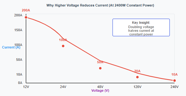
The accumulated values show how the higher voltage system delivers the same/equal or more power at a lower current. This is why they use high voltage to run solar arrays, EV systems, telecom infrastructure, and industrial equipment. By reducing the current, heat loss will be reduced and efficiency will be improved. It will also allow the usage of smaller conductors at longer distances. This table may serve as a planning reference for estimating current demand on various system voltages.
Accuracy & Limitations
The calculator assumes there is no change in the voltage and the power consumption of the equipment is constant. In most situations, the voltage drops when the batteries discharge or the inverters tune their output, or due to other circumstances on the grid. The wire and protection device can be overstressed when the voltage drops lower than the required level, and the power remains the same, as the current will increase.
In AC systems, the real current drawn by motors, compressors, and similar inductive loads may differ from that calculated, owing to the effect of the power factor not being taken into account. In addition, the inverter’s efficiency losses, cable resistance, temperature rise, and aging components all amount to the current actually being higher.
Therefore, the outcome from the V to A calculator should be treated as a basic calculated planning value. Typically, when engineers and installers are calculating wire sizes, breakers, and system components, they will apply some kind of safety buffer above this number to make sure the system operates reliably and safely in the field.
Case Study
A vehicle designed to service mobile equipment has 24 volts at the auxiliary battery for its diagnostic equipment and LED work lights, refrigeration storage for material, and multiple charging stations for tools. At peak operation, readings exhibit a combined load of around 860 watts for long ultimately.
Using the V to A conversion, the current demand is calculated to be 860 divided by 24, equal to almost 36 amperes continuous draw. At the beginning, the vehicle was wired with conductors having ampacity values close to these and was protected by a fuse with minimal capacity overhead.
As time passed, technicians began finding warm wiring insulation, intermittent trips of the fuses, and voltage sag at the terminals of the force equipment. These symptoms point to the idea that the actual operating current, along with wiring resistance and temperature effects, was beyond limits for the installation.
Following a proper load recalculation with a margin, the wires were changed to a thicker conductor size, and the fuse rating was altered, too. With the reduced voltage drop and no heating in the cable, equipment can operate consistently even during prolonged service.
This case illustrates volts-to-amps relationships to avoid thermal stress, improve reliability, and increase the lives of electrical components. The power source itself is not modified.
Conclusion
The V to A calculator is a reliable tool for performing volts to amps calculations from known power and voltage values. This straightforward relationship helps in safe cabling choices, correct breaker sizing, and reliable planning of batteries and inverters. Learning how voltage and power equate to a demand for current will enable users to design electrical and solar systems that operate efficiently and safely within the limits of components.
More Calculators for You
Solar Products for Your Project
Solar Panels | Solar System | C&I Battery Storage |
 |  |  |
Frequently Asked Questions
Divide the power in watts by the voltage in volts, and the result is the current in amperes required by the load and for more information, read the “formula and variable definition” section above.
Current determines wire size, breaker ratings, fuse protection, and battery discharge rates, and incorrect current estimation can cause overheating, hardware failure, and other hazards.
Yes, but in AC systems with motors or reactive loads, actual current may be higher due to power factor effects not included in this basic formula, and for more information, read the “formula and variable definition” section above.
If voltage decreases while power demand stays the same, current increases, which can stress wiring and protection devices.